PCB Maker
PCB Maker software, by NewRAD, lets you design your own PCB's (printed circuit boards) and then generate GCode for use in a CNC Machine to mill and drill a PCB at home, quickly and easily, and with much lower noise levels and much faster job times than traditional milling methods.
Download it here: PCBMakerSetup.exe (version 1.0)
Latest Revision: 12/10/2023When installing, Windows may give a security alert. Click on "More info", then "Run Anyway". Requires Full HD 1920x1080 screen resolution.; * After purchasing a license, you need to activate the license in order to access all the features that you purchased.
Features Free Version PCB Maker Design PCB Drawings Yes Yes Save PCB Drawings Yes Yes Generate Traces Yes Yes Generate GCode No Yes View GCode run in 3D Viewer N/A Yes Create you own components Yes Yes Generate And Print Toner Transfer
for etching PCB's with AcidYes Yes Generate And Print Solder Mask
for using with UV paintYes Yes Create Project files for sharing your ideas. Yes Yes Price Free 149.95
Purchase a license here ==> Click "Buy Now" button ==>
How To Activate License After Purchasing
To activate your license, run PCB Maker software, click on the Tools menu, then click Activate License and enter your Paypal address. You should then get a message box that says "Thank you for purchasing PCB Maker", and your software will then be activated for full usage of all features purchased. Thank you for purchasing!
PCB Maker changes the process of designing a circuit, creating the GCode, and milling the PCB on a CNC machine from hard, complicated, slow, and noisy, to easy, simple, fast, and much quieter.
Design your circuit Mill and drill your PCB
PCB Maker generates GCode for scratch milling PCB's using a scribe bit, that runs with very high feed rates, but with lower spindle speeds for much less noise.
PCB Maker is mainly about 5 things that change the process for making a pcb at home, from a horrible process to a great process, that is actually enjoyable for the first time.
1. Easy-to-use PCB design software, that is also fun to use since it has by far the best component graphics of all the competition.
2. Generate GCode Directly From PCB Drawing. One-Click Generation of Traces, One-Click Generation of GCode. Zero mental energy needed and the GCode is perfect every time, unlike using Eagle with FlatCam which is hard and takes forever and requires a ton of mental energy, and which is very easy to make a mistake in, and thus ruin the entire job and have to start all over, which can be very frustrating and demoralizing. The amount of time and mental energy saved makes PCB Maker worth purchasing, with no doubt. It pays for itself after just a couple of jobs, and then it is yours to use forever. Not to mention the reliability of a one-click process that is impossible to mess up. Perfect GCode every time. Each time you use PCB Maker, you save a ton of time and mental energy, compared to any other method out there that we have seen, and we think that we have seen them all. If you are using FlatCam, then it is time to switch to PCB Maker.
3. GCode generation with two modes, slow VBit or fast Scratch Milling with a Scribe bit, each with customizable settings that can be saved. Scratch milling with a scribe bit allows for much faster feedrates and thus quicker job times, plus the ability to mill using slower spindle speeds, which is much LESS NOISY. The feedrate is fast, so the job gets done quickly, while the spindle rate does not have to run at a high rpm rate, and thus the process is much less noisy. Plus scribe bits are much cheaper, safer, and more durable than V-bits, and can be resharpened, and reused, thus saving a lot of money in the long run.
4. PCB Maker puts all the GCode jobs of milling and drilling different holes sizes into just one file. When running the job, it will raise up the Z axis to be able to change bits, and then stop the program with an "M00" code. Just change the bit, and re-zero the Z axis for that bit, the continue the job. This allows for super easy operation with any CNC Controller.
5. Special additions to the GCode that help ensure there is no copper debris left in the traces. FlatCam does not do this.
PCB Maker is a Game Changer
PCB Maker + Scratch Milling with a Scribe bit = Game Changer
Why PCB Maker is the right PCB design software for you
First, the PCB Maker software itself and why it is the right software for most people. It is designed for the typical home electronics hobbyist type person, ...people like you and me, and not the professional electronics circuit design engineer who is designing circuits for a large company that is making tens of thousands of copies of that PCB. Most PCB design software is designed for professional engineers in the corporate market. They produce Gerber files, and not GCode files, and are simply not made for hobby users, unless the hobby user wants to go through the laborious process of sending Gerber files to China and wait 2 weeks, and pay money to do so, and when you finally receive your pcb, if there is a mistake, you have to start the 2 week process all over again. Up until now with PCB Maker, hobby users that wanted to produce GCode had to install other software like FlatCam to convert their Gerber files to GCode, and it is a very long drawn out process. It is also a stressful process, because it is easy to make an error during that long drawn out process. It also produces multiple GCode files and requires moving files around on your computer manually. The entire process is horrible. It takes a lot of mental energy, and is highly prone to human error. Plus it does not create the added GCode tricks that PCB Maker does, that make all the difference in eliminating shorts in the PCB. PCB Maker is ideal for the hobby electronics user of today. They like to use Arduinos and other processor boards designed for the hobby electronics market. PCB Maker includes graphical components for all the popular processor boards that you already know, like Arduino, etc. Professional electronics engineers do not use Arduinos in their circuits, and almost all of their work is with tiny SMD components these days. SMD components are designed for machines to work with, not humans. PCB Maker is design for through-hole DIP chip type components, so it is ideal for Arduino users, and for making any through-hole type PCB. PCB Maker is made for people like you and me, and not the professional electronics circuit design engineer that wants to use tiny SMD components and produce Gerber files, instead of GCode files. Electronic hobbyists using Arduino type processor boards want to mill a PCB immediately on a CNC machine at home, and therefore, they need GCode files, not Gerber files. PCB Maker does what the hobbyist needs. All of these advantages is why PCB Maker is the right software for you, and is very much worth the investment. The investment will last indefinitely, as through hole components are not going away. Plus all the included components are current and up to date.
PCB Maker is ALL NEW and CURRENT
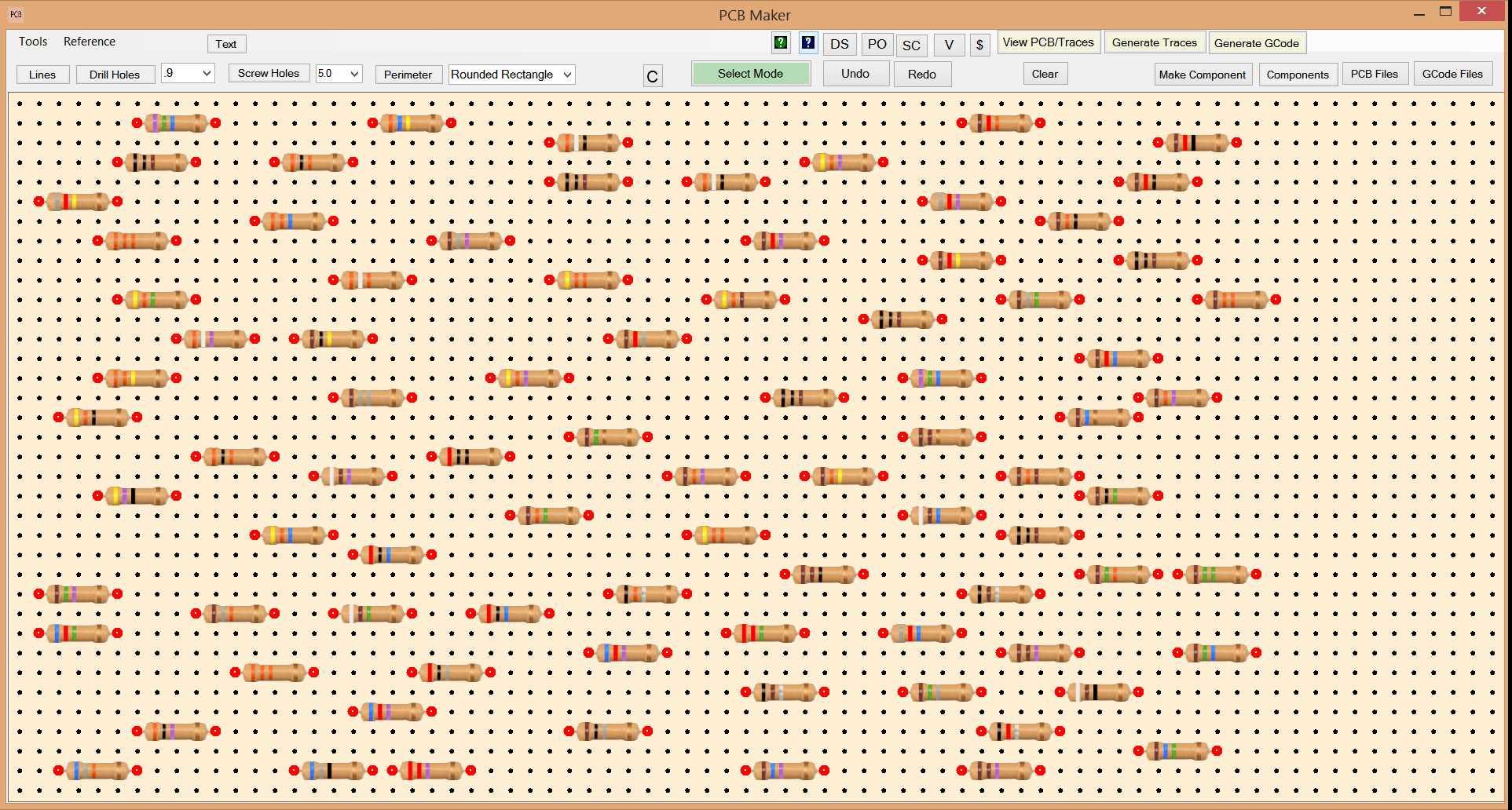
PCB Maker software. released to the public May 10, 2022, is all new, and has amazing real life graphics for all the current commonly used electronic components and modules that you see being used today on youtube, and that you currently see for sale at major websites. Having nice looking graphical representations of all those components that you are already using, makes PCB Maker really fun to use. The graphics also makes it EASIER to use, as you can now see exactly what you pcb is going to look like on top, and on bottom.
Amazing Real Life Graphics (fake circuit)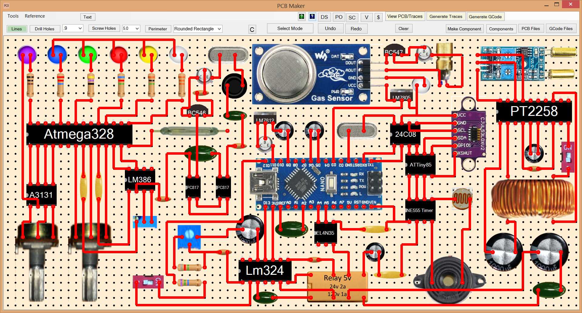
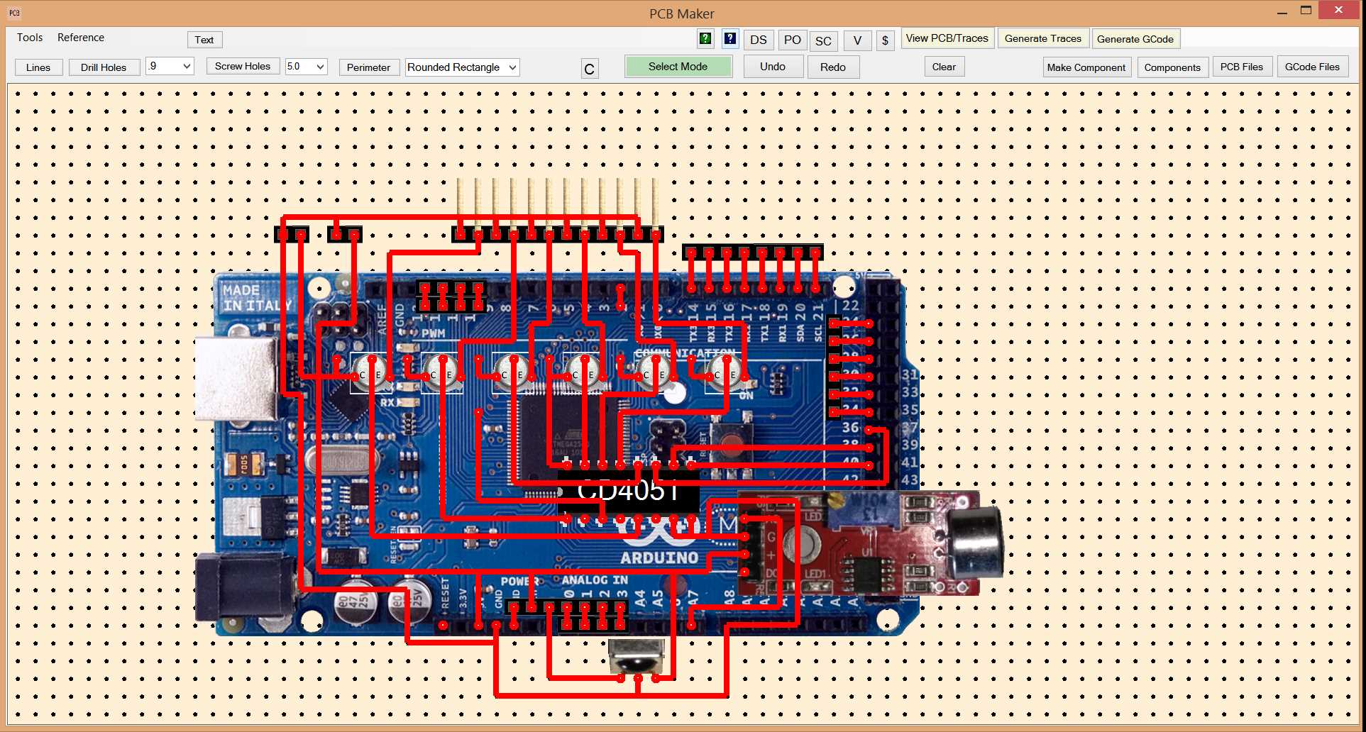
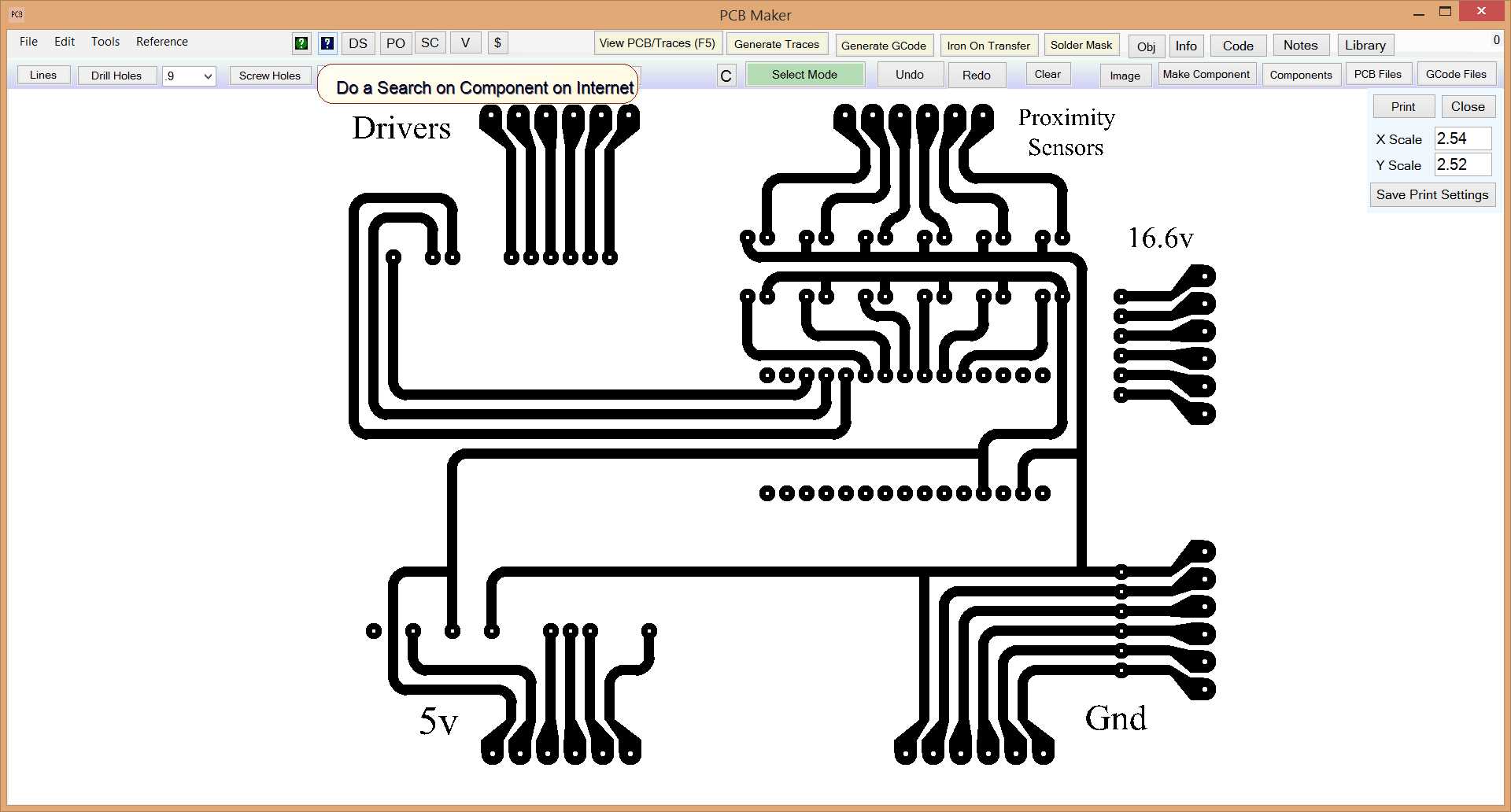
Second, PCB Maker software allows you to generate the pcb traces with one click, and you can go back and forth between viewing the traces and the circuit design instantly, with just a click, so you can see exactly what the pcb is going to look like, right then and there, and in the same software that you used to design the pcb. This can be helpful at times when considering the physical aspects of a design. You do not have this advantage when using Flatcam where you do not get to see your traces until after a bunch more work, and not even in the same software that you used to design the pcb. Flatcam is a pain, and a mistake waiting to happen.
Generate Traces with One Click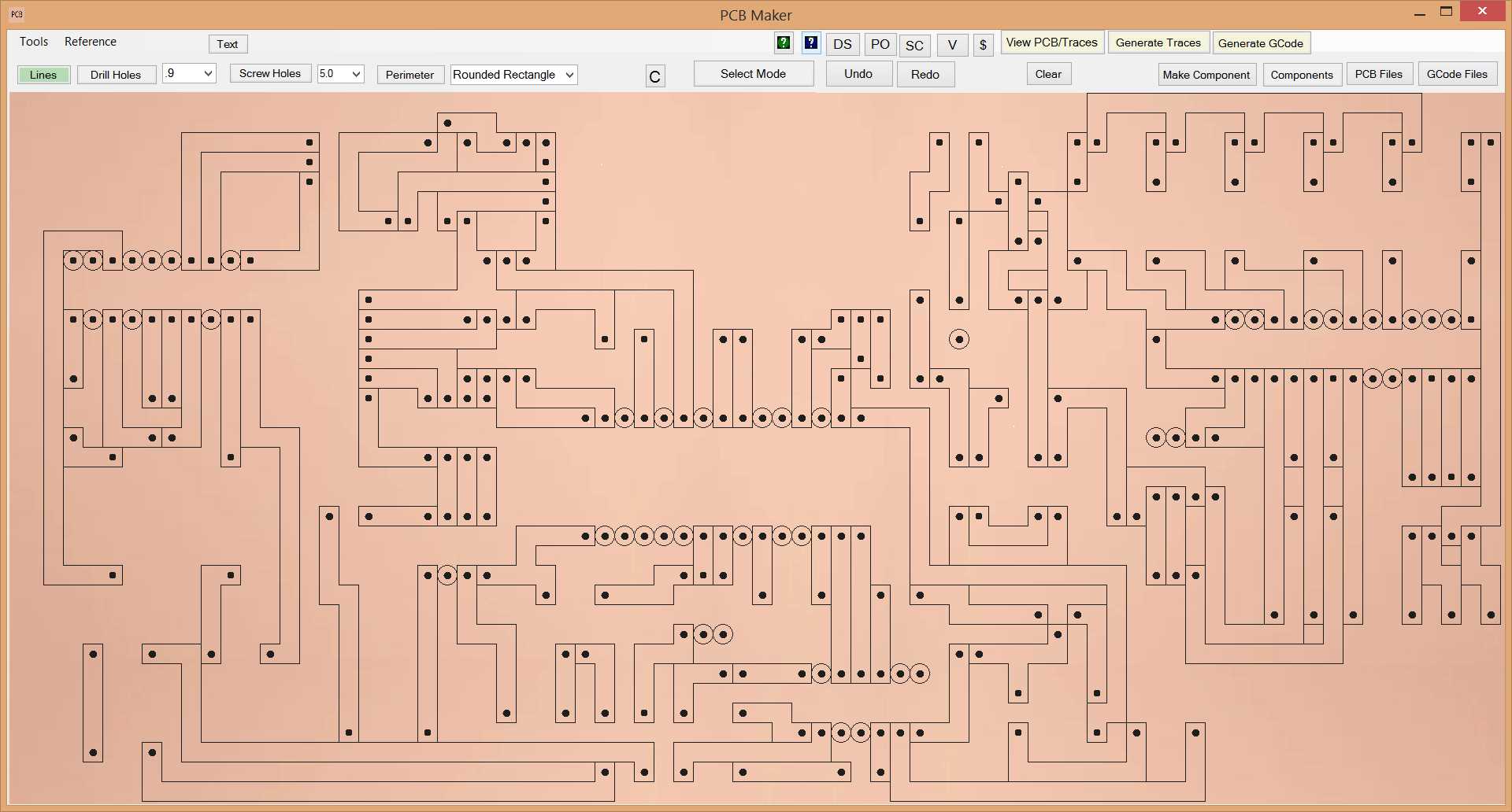
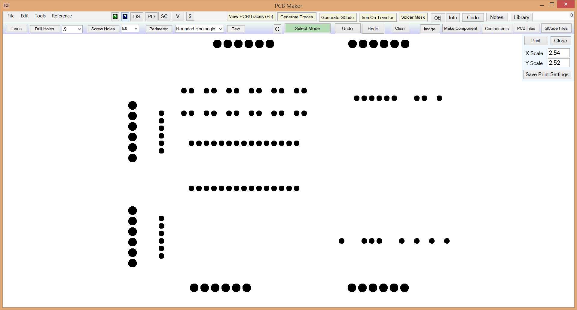
Third, the ability to Generate GCode with one click, and in the same software that you used to design the pcb. This is much easier than using Eagle PCB or other pcb design software where you have to first generate Gerber files, and then importing those files into FlatCam, and then generating various GCode files, and having to then manually move those GCode files to the GCode folder of your CNC controller software. PCB Maker lets you generate the gcode with one trick, and the GCode file will automatically be copied to the NewRAD CNC software's GCode directory if installed. No thinking or human intervention needed.
Generate GCode with One Click
Note in this example, the GCode was generated using the multi-pass option, lowering the Z by .02mm on the second pass.
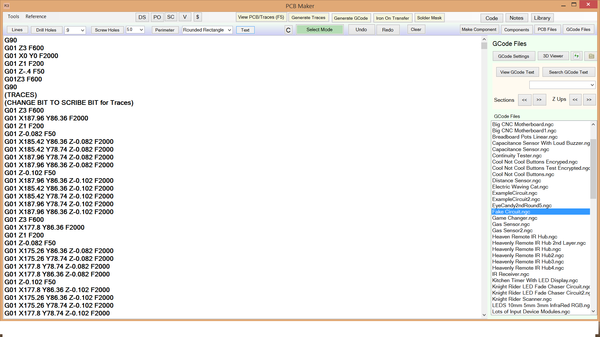
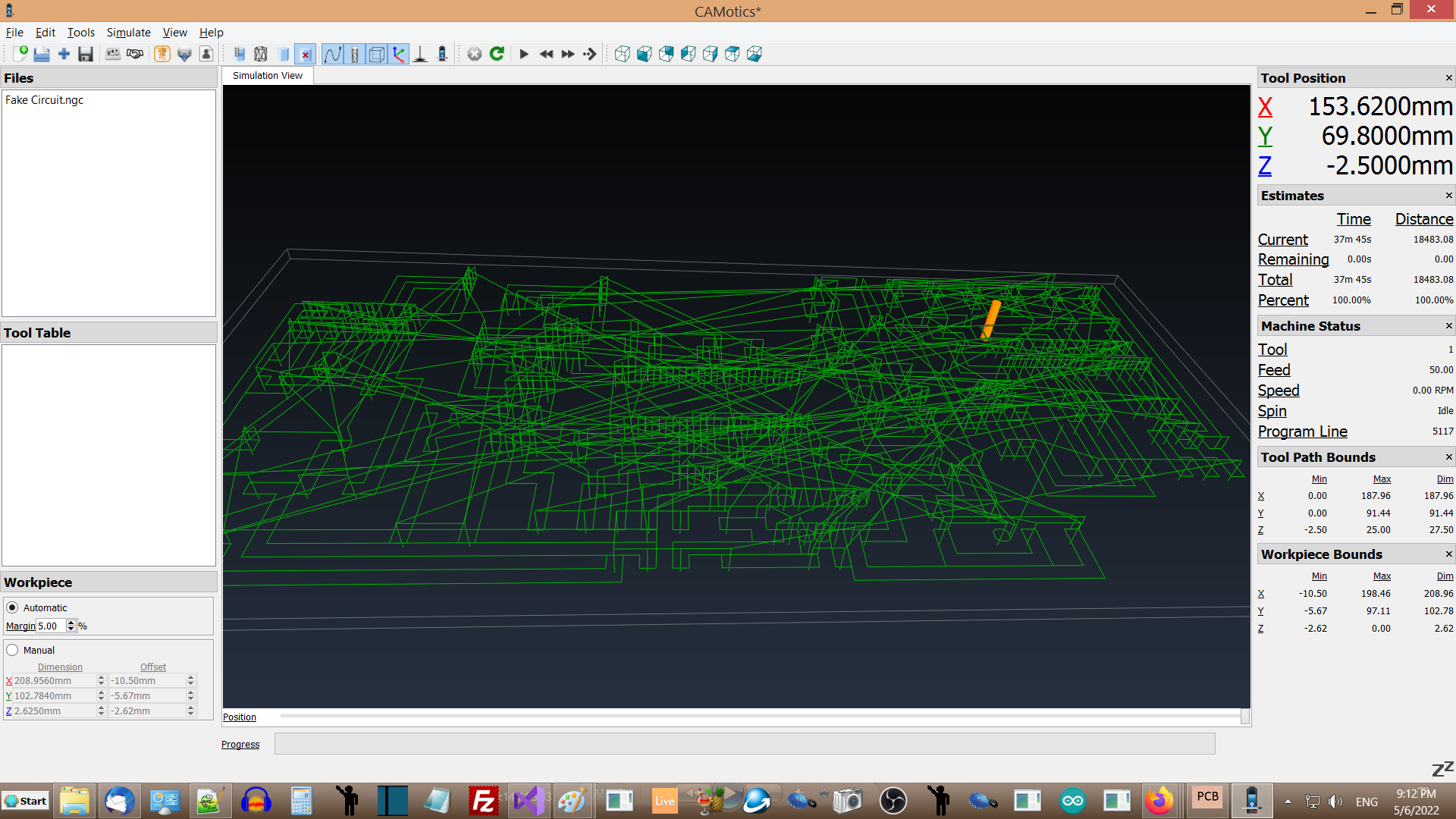
View Generated GCode in 3D Viewer with One Click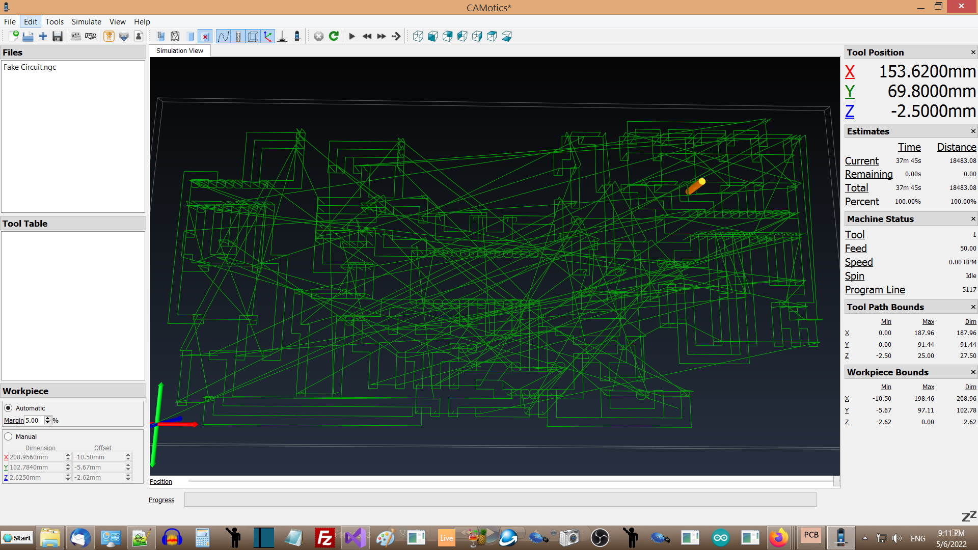
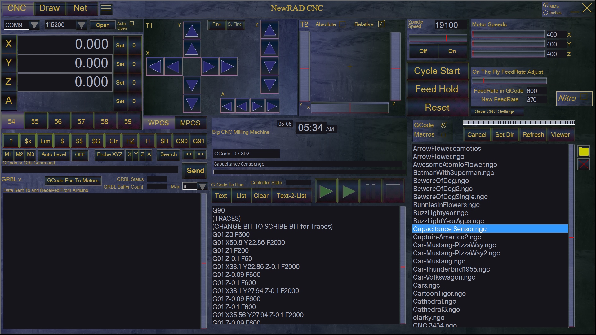
Fourth. Seamless integration with NewRAD CNC. When generating GCode, PCB Maker will generate the GCode file to PCB Maker's GCode Files directory. If NewRAD CNC is installed, then it will automatically make a copy of that file and send it to the GCode Files directory in NewRAD CNC. When you go to NewRAD CNC, that one GCode file will be waiting for you. Just hit the "Refresh Files" button in NewRAD CNC and you will see the newly generated GCode file ready to load. This is a very convenient feature, and it makes it faster and easier to use. It saves a lot of time and energy that would otherwise be wasted copying files from one location to another, like what often happens when using two non-integrated systems from two different manufactures.
NewRAD CNC
Fifth. The ability to generate GCode specifically for scratch milling with a scribe bit, that runs with very high feed rates for much lower job times, and with lower spindle speeds for much less noise. Less noise, faster job times. It's a game changer. Having lower noise levels takes all the stress out of the process for the user. The other main benefit is dramatically reduced trace milling time due to a feed rate that is 15 times faster than traditional milling with using a V-bit. It feels almost like 3D printing, instead of milling. For the first time, it is actually enjoyable and fun to mill a PCB on a CNC.
All of your Favorite Processor Boards
PCB Maker has all the processor boards that are commonly used like Arduino Uno, Nano, Mega, Mini, Pro-Mini, NodeMCU, ESP8266, STM32 Blue Pill, STM32 Black Pill, Raspberry Pico, etc. It has all the common sensor modules and other types of commonly used modules like input modules, output modules, audio amplifier modules, relay modules, camera modules, drone modules, and general use modules like real time clocks, battery chargers, power converters, etc. Plus all the common traditional analog electronics parts like resistors, capacitors, IC chips, transistors, voltage regulators, inductors, relays, buzzers, LED's of all sizes and colors, potentiometers, crystal oscillators, switches, buttons, etc. It has beautiful resistors, that we took extra time to make look perfect, with the perfect colors and sheen from light reflection. For some of the resistor band colors, we actually used slivers of images of coffee cups and them turned them 90 degrees so that the light sheen was in the correct place. It worked quite well. We had to create our own graphics software for internal use to help create our component graphics. We also had to create generators to create these graphics for many of the different types of components where the graphic is the same or similar, but the component value is different. We had to create graphics generators for specific components, like our resistors. All of these graphics were very expensive to make, but they increase the overall level of fun and ease of use, and they make it easier to understand the circuit, and to communicate the circuit to others who may want to reproduce it. Plus there are component generators in the Tools menu in PCB Maker that allow the user to make their own Chips and Transistors easily, that they can later add to their PCB Drawings.
Includes all of your Favorite Processor Boards
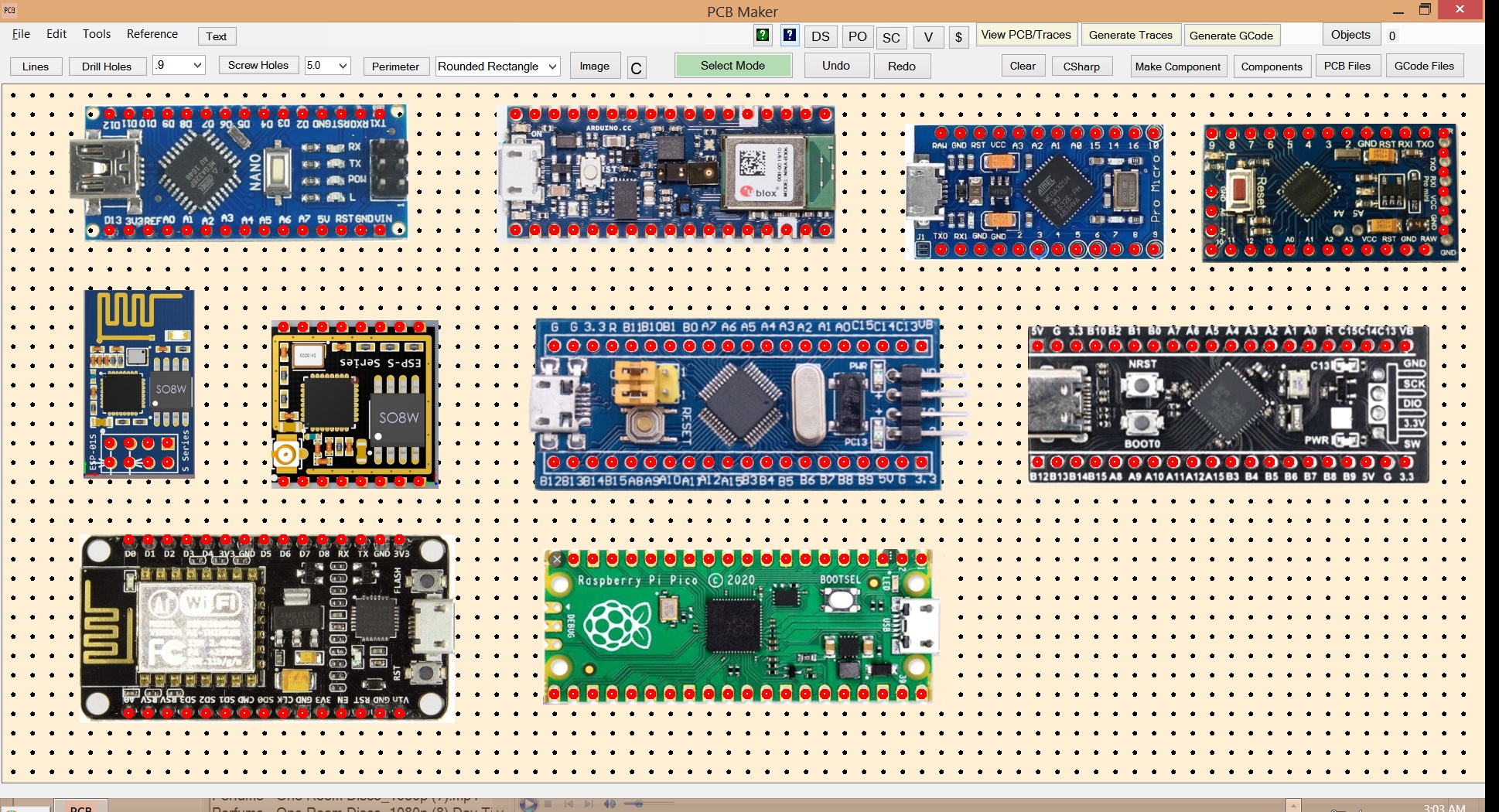
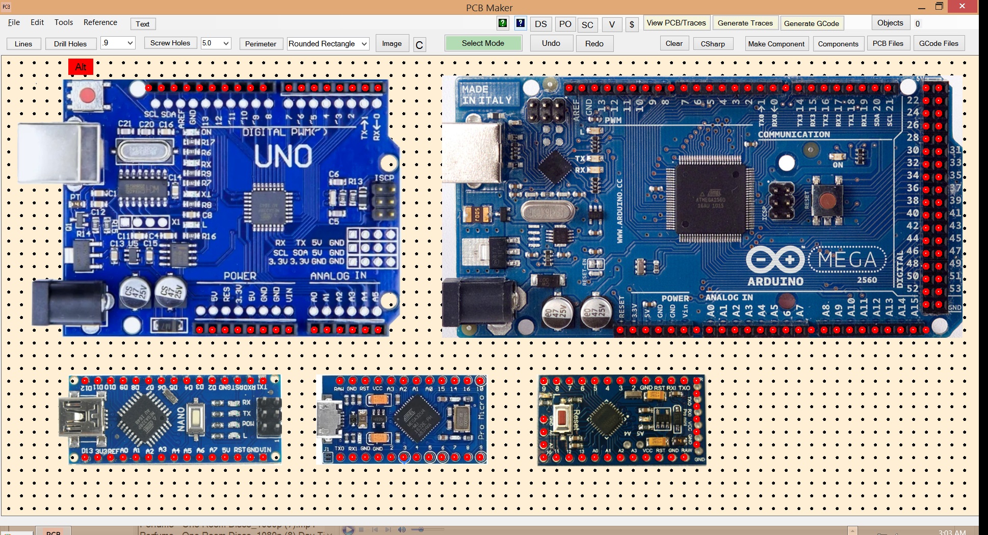
Includes the Most Commonly Used Arduinos
PCB Maker works especially well with NewRAD CNC
PCB Maker works especially well with NewRAD CNC, our GRBL Controller software, which has a high-precision "Auto Level" feature, which is critical for milling PCB's.
Generate GCode for V-Bits or Titanium Carbide Scribe bits.
PCB Maker can generate GCode optimized for "scratch milling" using a titanium carbide scribe bit, or more traditional milling using a V-Bit, which is much slower and much noisier, and therefore we consider it to be obsolete, except for boards with very smal traces like for SMD components.
V-Bit Scribe Bit Super Slow, Super Loud and Noisy Fast, Much Quieter Evil Good V-Bits Kill Scribe Bits Save Lives
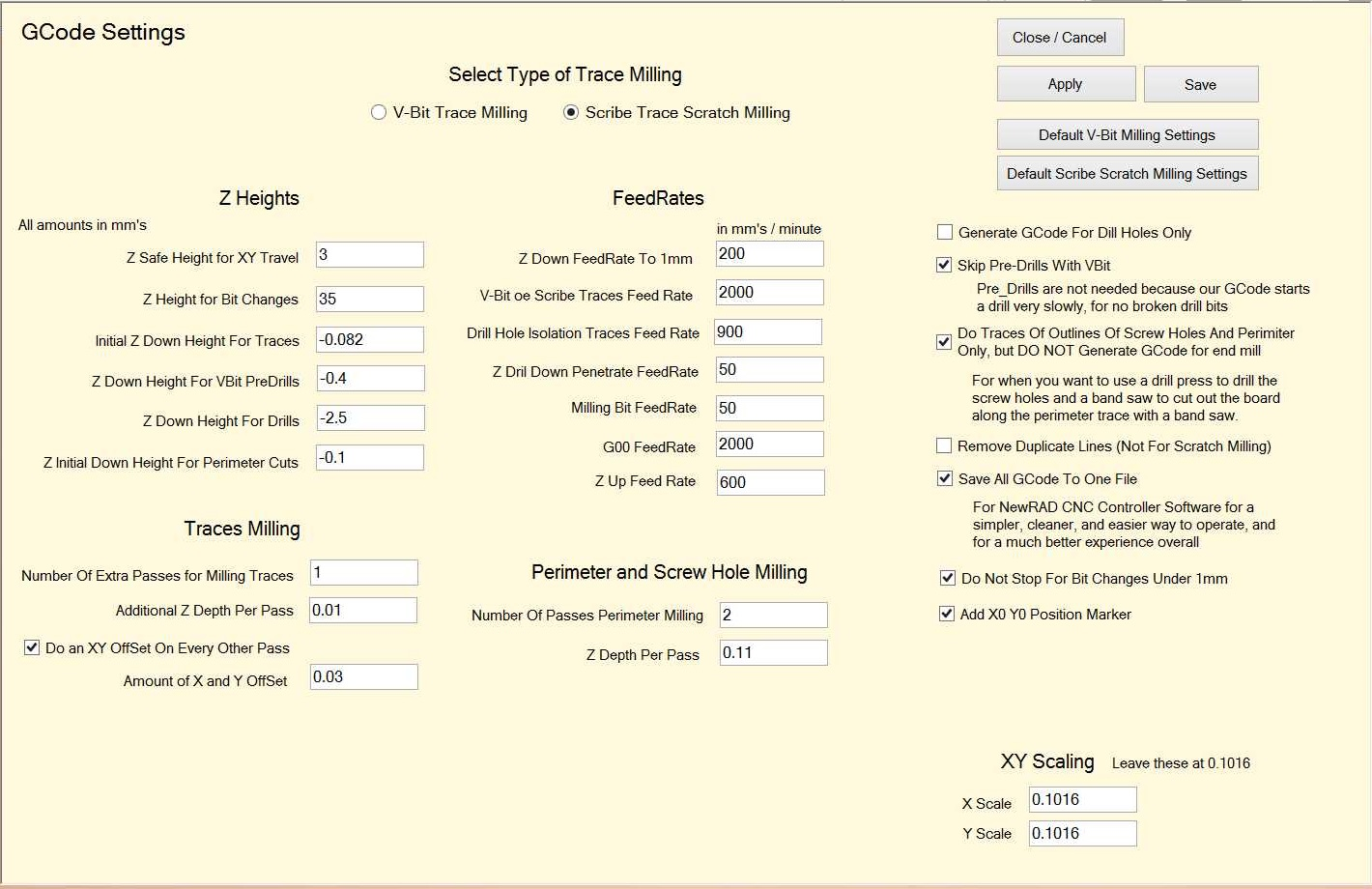
Powerful GCode Settings Screen
PCB Maker has a very elaborate GCode Settings screen where you can save your GCode Settings for both Scribe bit and V-bit modes of operation. There are also buttons for easy recall of our default settings for both Scribe bit and V-bit modes of operation. The GCode Settings has options for saving all the GCode to one file for much easier, seamless operation using the NewRAD CNC controller, or to many files for use in other controllers like Mach 3, or Mach 4, however, that is a much harder process to manage.
What is Scratch Milling with a Scribe Bit?
Scratch Milling uses a FAST scratching method of cutting the traces into the copper, instead of a traditional milling a pcb with a V-bit that is super SLOW, and the fragile V-bits are very prone to breaking, unlike a scribe bit which is unbreakable. The spindle is still turned on in order to clear out the material from the traces, but the actual cutting action is from scratching. Since the cutting action is done by scratching using an unbreakable scribe bit, instead of milling with a fragile V-bit, this allows you to run the machine way faster than you could ever dream of with a V-bit, thus essentially making milling PCB's with V-bits obsolete, except for when working with super fine traces, like SMD.
MUCH LESS NOISE using scratch milling with a Scribe bit!!!!
Since the cutting action is done by scratching, and not milling, this allows the spindle to run a much lower RPM's which is much quieter. The spindle RPM's can be reduced from 10000 or higher, all the way down to about 6500 HPM's, thus decreasing the noise by approximately 75 percent. It is much less noisy, much less stressful, and way more enjoyable.
Drilling the holes can also be done with about 6500 RPM's. The amount of noise a spindle puts out at 10,000 RPM's is about 3 to 4 times louder than at 6500 RPM. With a sound proof box for your CNC, and some music playing at a moderatete volume, you can be milling PCB's in your apartment at 11pm at night, without anyone even knowing. And do the whole thing, milling and drilling, in less than 20 minutes. At night. In an apartment. This is a game changer.
Don't believe the hype! ...of Wegstr and others on youtube
You see beautiful pcb milling videos on youtube by companies like Wegstr and others where they show you a VBit moving quickly and with beautiful classical music playing in the background, with beautiful lighting, like everything is all wonderful. Except it has nothing to do with reality because the video is sped up like 8 times faster than in reality, and the noise that a spindle makes when running at 10,000+ rpms, is a horrible nightmare. It does not sound like classical music at all. So in reality, it takes forever because the machine is really moving at 1/8 the speed of the video. So you have this horrible sound for a hour, or who even knows how long it takes. They never talk about how long it takes or the horrible noise. They just leave that part out completely.
MUCH LESS TIME TO MILL a PCB
Since you can run the machine at surprisingly high feed rates with scratch milling, you can scratch mill a fairly large pcb, say 8cm X 14cm, in only about 10 minutes. And another 10 minutes to drill all the holes.
The Results are Fantastic!
The results are milled PCBs with NO SHORTS in minutes. And with LOW NOISE, Quick Job Times, Low cost, unbreakable scribe bits that are stress free to handle, unlike V-bits which are scary to handle. No Time Wasted in the process, like when using FlatCam, No stress of making a mistake like with FlatCam. Easy mindless CNC operation when using PCB Maker with NewRAD CNC controller.
Using PCB Maker with NewRAD CNC controller, with Auto Level on, we have been able to mill one fairly large pcb after another, at high feedrates of around 2400mm/minute, a low spindle speed of about 6500 rpm, with NO SHORTS. We do not even need to sand the pcb's copper backing to remove burrs, as there are none. All we do is use a stiff brush under running water to brush away and wash away any copper dust or debris that may be left in the tracks. We prefer not to sand the pcb, as it never looks as good afterwards.
Multi-Layer PCB's
Adding a second Layer PCB to the first layer PCB, ...and beyond.
Adding a 2nd Layer PCB to the first layer is the equivalent of a milling a 2-sided PCB, but without all the hassle or special setup required. Milling 2-sided PCB's is a very difficult, stressful, and horrible process. You first need a special pcb workpiece holder with 4 stationary location pins, so that you can flip the pcb, while maintaining alignment. Then you need to mill or drill 4 alignment holes in the 2-sided pcb blank using a CNC machine, so that the holes will be the exact width that they are on the pcb workpiece holder. You have to do this big messy step every single time, for every 2-sided pcb that you want to make. Just that process alone adds a big messy extra step that throws a lot of dangerous-to-breathe pcb material dust into the air, and all over your CNC machine, unless you have a great vacuum system on your CNC machine. After that, then you have to mill one side of the pcb, flip it over and mill the other side. And then you have to insert and solder little metal inserts to carry the connection from the top side to the bottom side. It looks nice and is an elegant solution, but is difficult to manage all that complexity of working on the back side of a pcb, with everything flipped over.
Our easy solution for 2-sided PCB's is to just add a second layer pcb, and use male and female headers connect the first and second layer as you would an Arduino shield with an Arduino. It is less compact but usually that is not a problem for most projects. The main thing is that our solution of a 2nd layer PCB is just much easier to do, than trying to mill and drill a 2-sided pcb, that is milled on both sides. Easy is good.
If your PCB only needs just a few bridges, then the easiest solution is to just use jumper wires. But if it is say 6 or more jumper wires, milling a 2nd board starts to become an attractive option. PCB Maker makes that easy to do. For most hobby electronics projects, there is nothing wrong with having a 2nd pcb that snaps in to the first one, like an Arduino shield does with an Arduino. The connection made is very reliable, and can take a lot of jolting movement, like even in an RC car, and still work. Usually the added size of stacking 2 pcb's is not of concern, and most projects do not take a lot of jolting movement, so the male/female header connections are usally never a problem for maintaining reliable connections. To us, milling a 2nd layer pcb is much easier than trying to mill a 2-sided PCB, plus there is less risk involved. If something goes wrong with a 2-sided PCB, then you could potentially lose twice as much work. For us, working with 2 separate single-sided PCB's is much easier than trying to make a 2-sided PCB. Plus many problems can occur from having copper on both sides on a PCB. Many solutions try to mill away large amounts of copper, which is a long time-consuming, horribly-noisy, and messy approach. We much prefer our solution of simply adding a 2nd layer PCB that snaps on to the 1st layer with headers, just like any Arduino shield. It makes everything easy, with much less mental energy used, and since it is much less risky, it is also much less stressful too. Hobby electronics should be fun. Decreasing the amount of stress and mental energy required is a huge benefit to all users.
How to Make a 2nd Layer PCB
To add a 2nd Layer PCB to your "1st layer" PCB, load your 1st layer PCB drawing, then click the "Tools" menu, and then click the "Make 2nd Layer PCB Board On Top of Current PCB Image" menu item. The software will make a picture of the current "first layer" PCB, and then paint a semi-transparent PCB top-side color on top of it, so that you can see the first layer in order to line up the 2nd layer, but without the first layer interfering with what you are focused on putting on the 2nd layer. You can clearly see the washed out appearance of the first layer to denote that it is in the background, and not part of this 2nd layer PCB design. And lines and drill holes and components to the 2nd layer just as you would any PCB. Then just save the 2nd Layer PCB, generate traces and then generate GCode,...just as you would with any PCB. Add female headers to the 1st layer pcb, and male headers to the 2nd layer, and then the two pcbs will fit together securely like an Arduino shield on top of an Arduino. This 2nd Layer PCB solution is so much easier than messing around with 2-sided PCB's, and all that complexity, risk, stress, and mental energy used in that process. And all that extra PCB dust. It's no contest. PCB Maker's solution is far easier and better, for the vast majority of hobby electronics needs.
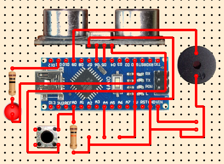
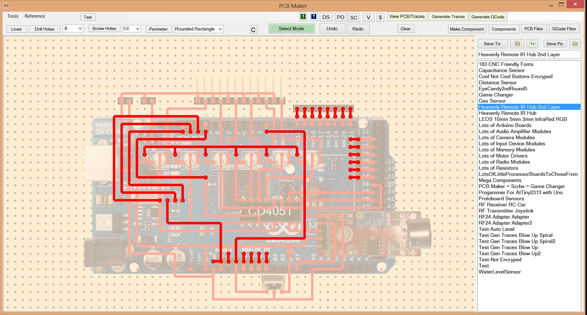
1st layer PCB
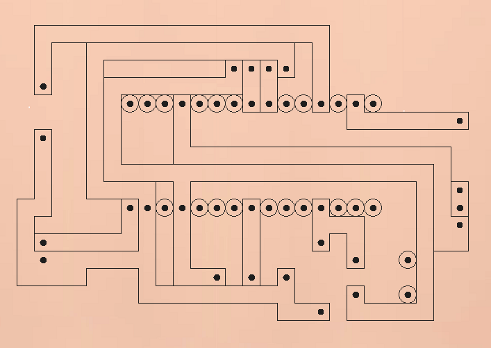
1st layer PCB Traces

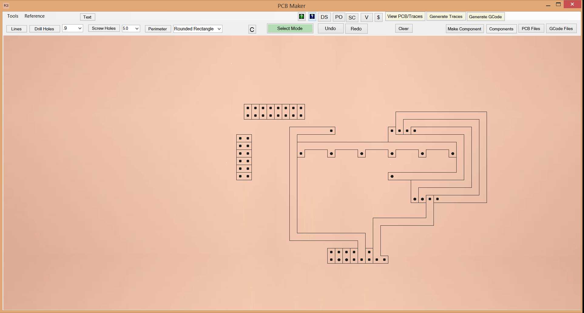
2nd layer PCB
2nd layer PCB Traces
What if I am using a component that is not included in PCB Maker?
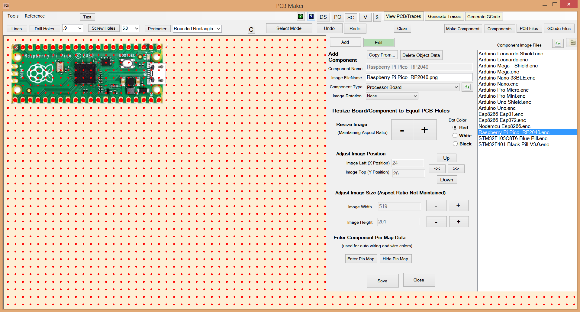
No problem. PCB Maker has a "Make Component" screen that lets you take a ".png" image file of the component that you want to add, import it into the Make Component editor screen, then use the buttons to resize the image so that the pins on the component line up to the red dots on the screen, which are equal to the standard DIP component of 2.54mm (1/10th of an inch) pin centers. Then just add drill holes as needed.
Make Component Screen
How to Make your Own Components
To make your own component, click the "Make Component" button. Then click the "Add" button at the top of the Make Component panel. Select the Component Type in the drop down listbox. It will the display a list of ".png" files in the corresponding component image subdirectory for the selected Component Type. Then click the "Open Folder" icon button and it will open a Windows Explorer to the image directory that corresponds to that Component Type. Just paste a ".png" file of an image of your new component into that directory. Return to PCB Maker, and click the Refresh button in the top right corner to refresh the list of image files, and your .png file will appear in the list. Double click on it and your component image will appear on the screen. PCB Maker will draw little red dots on the entire screen to represent a grid matrix pin spacing. Using the size and location buttons in the Make Component panel, simply size your image to be equal to the grid's pin spacing, add drill holes, and save. The component will then be ready to use just like any other component included in the software.
You can also skip the making of a new component graphic if you want to, for when it is better just to skip it.
If you really don't want to bother with making a new component, then no problem. You can simply just draw the component's drill holes where where you want, and just skip the graphic altogether. If you were trying to share your PCB with the world, then it would be better to have the graphic, as to communicate your PCB design better, but it is not needed to make a PCB. But it sure looks nice on the screen. It makes it easier to understand your own pcb drawing later on. But for times when you just don't care about having a graphic, on something simple and quick, you could just skip it. Usually you will not even need to add any new components. So many components are already included.
Special Screens for Easily Adding your own Chips and Transistors
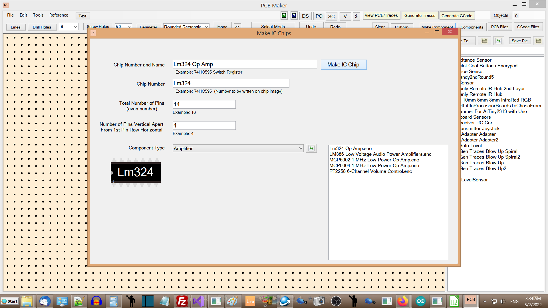
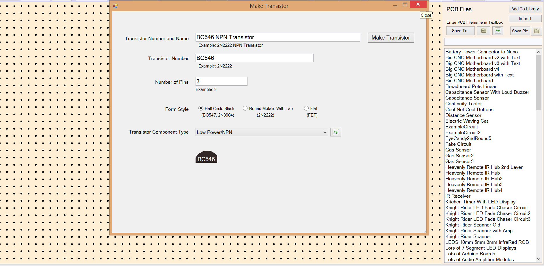
You could just use the "Make Component" screen to make a new chip or new transistor, one that is not included in the software, ...but for Chips and Transistors, we added special screens for adding those easily, without having to worry about obtaining component images, resizing them to the grid matrix, and adding drill holes. These special screens will do all of that for you in just one click. For chips, just type in the chip name, chip number, and number of total pins, and the width between the 2 rows of pins expressed as a number of pins for the width. Then click the "Make Chip" button, and your chip will be made and be ready for use. For transistors, just type in the transistor name, number, and select which type of package you want, and then click the "Make Transistor" button. Your transistor will be generated, and will be ready for use, just as if it was included in the software.
Most of the commonly used chips and transistors are already included in the software, so you should not have to make many of your own chips, transistors, or other components. It already has just about everything you will ever need.
Make IC Chips Screen
Make Transistors Screen
Lots of Up-to-date Components to choose from included.
All kinds of Components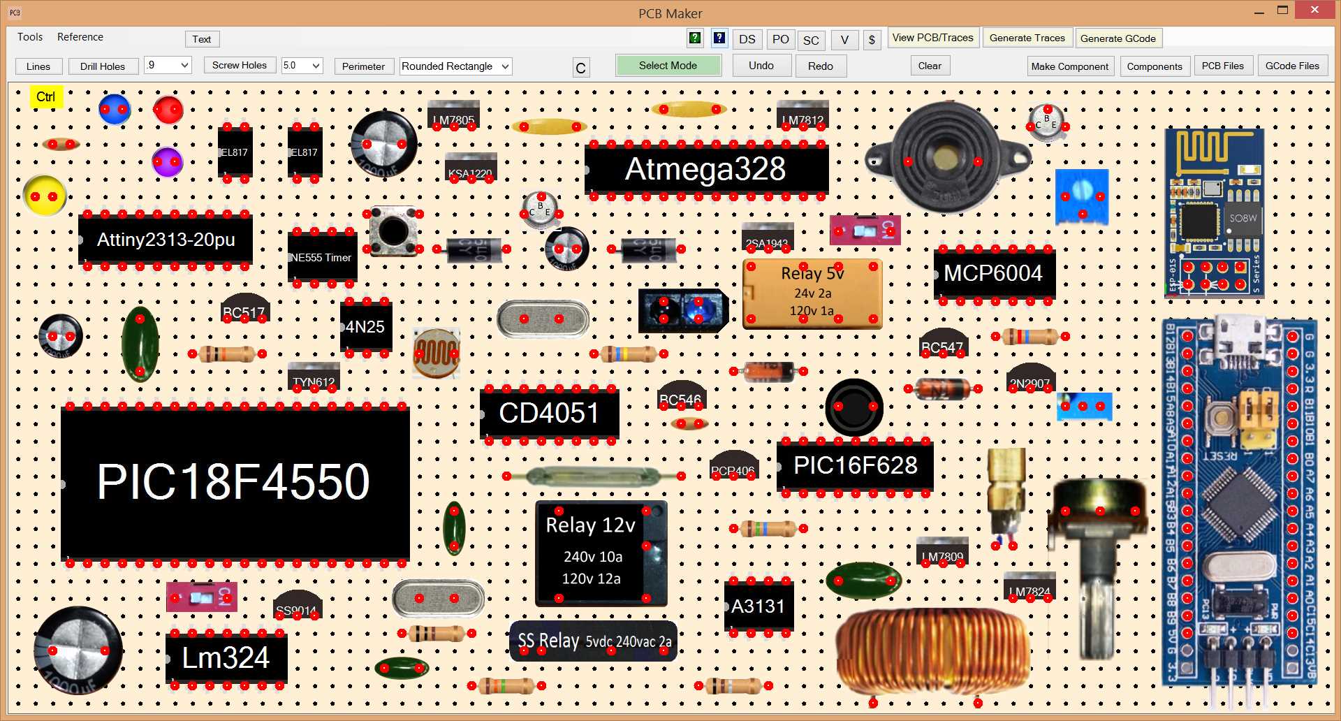
Sensor Modules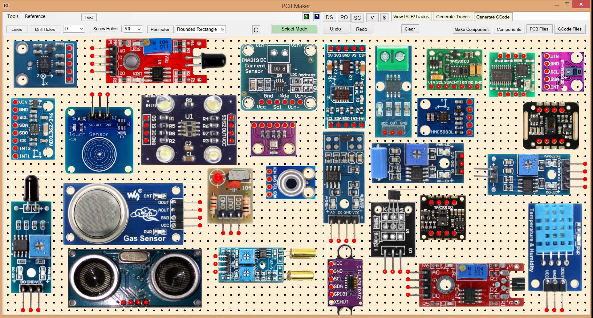
Radio Modules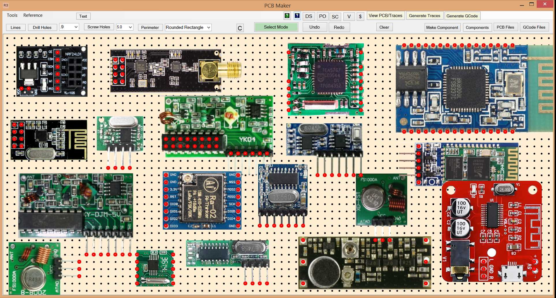
Motor Drivers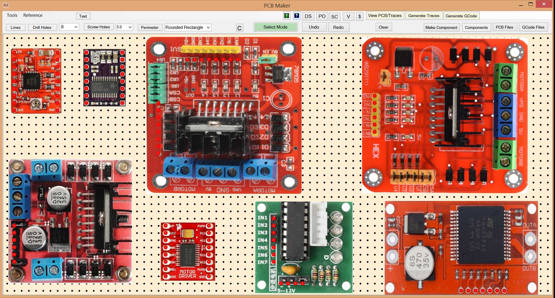
Input Devices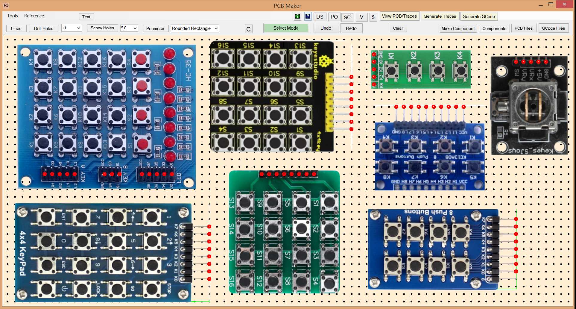
Camera Modules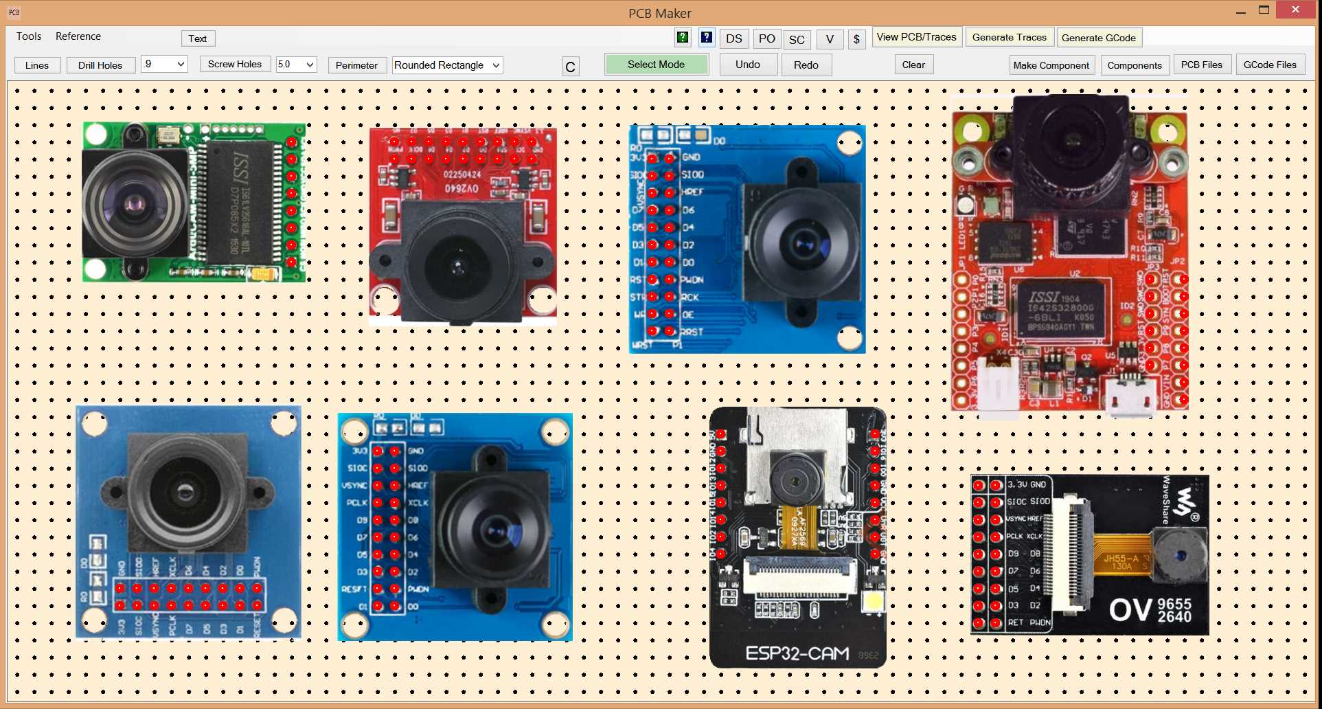
LEDS 3mm 5mm 10mm, InfraRed, and RGB (4 pin)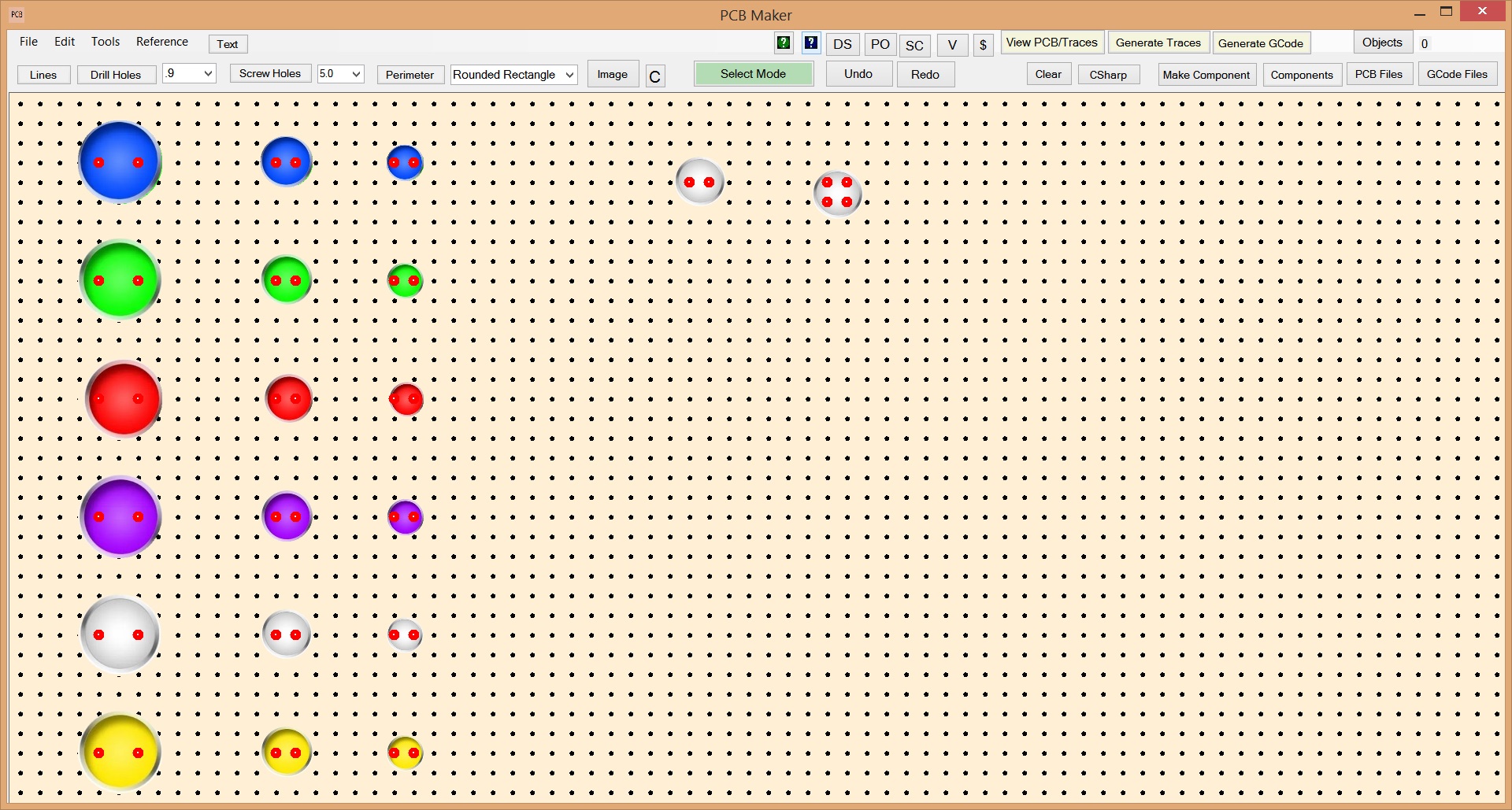
Our Beautiful Resistors
These took a lot of hard work to make with this quality of graphics, the correct light reflection sheen on the resistor body and color bands, with the right texture, and with a high precision of color in the color bands to make sure that the user can distinguish one color from another color that is similar. So even though the resistor is very small, the user can quickly tell red from orange, blue from violet, yellow from gold, silver from gray, brown from black, etc. We had to build our own color adjuster to do that. Some of the color bands were actually made from images of coffee cups, turned 90 degrees, so we could get the perfect light reflection sheen, with the right texture, and with a color that was close enough before fine tuning it with our custom made color adjuster. This attention to detail is inherent all the way through in PCB Maker, and in all of our CNC software products.
Memory Modules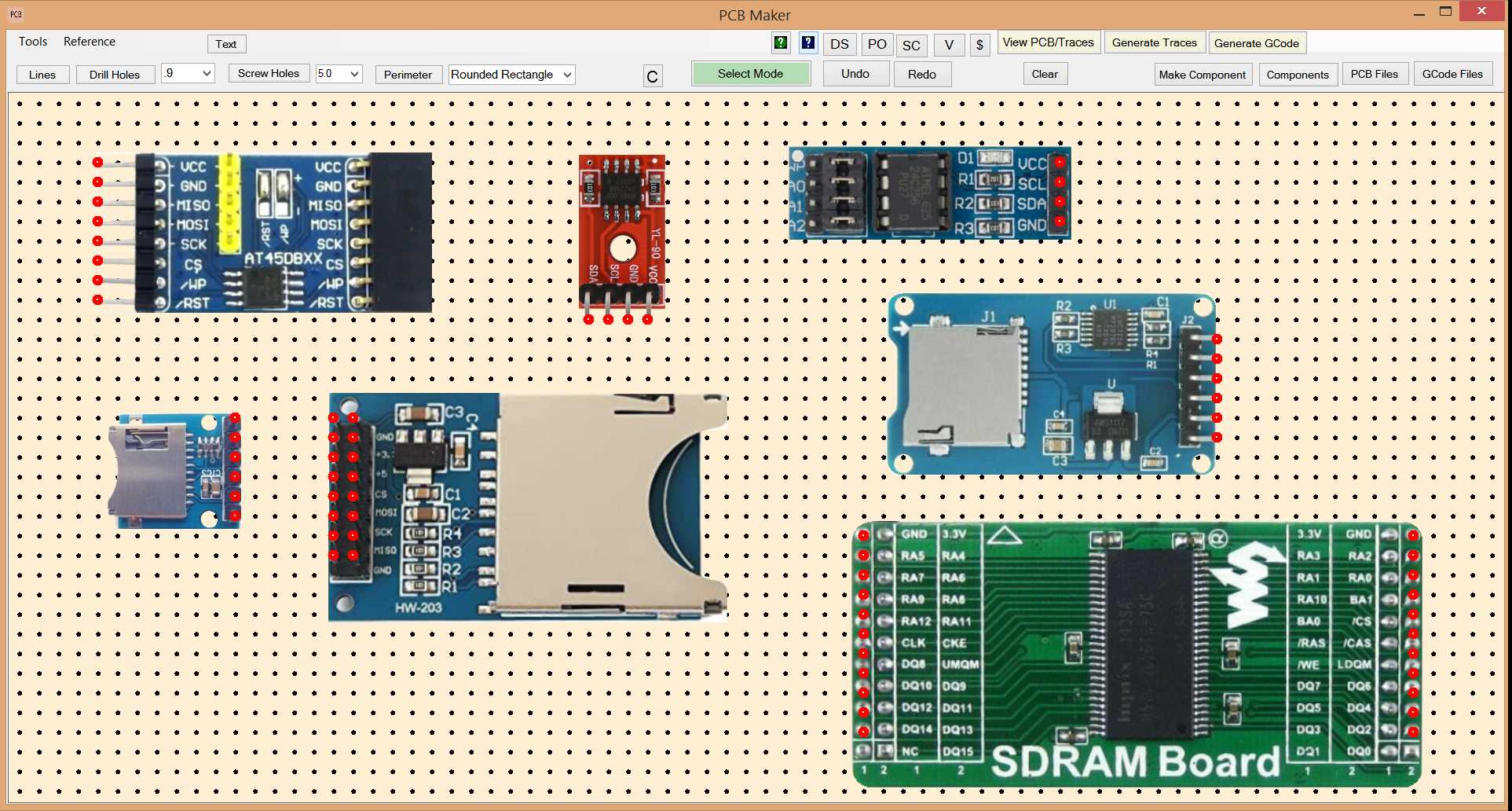
163 CNC-Friendly Fonts
PCB Maker comes with 163 built-in fonts specifically tailored for CNC usage.
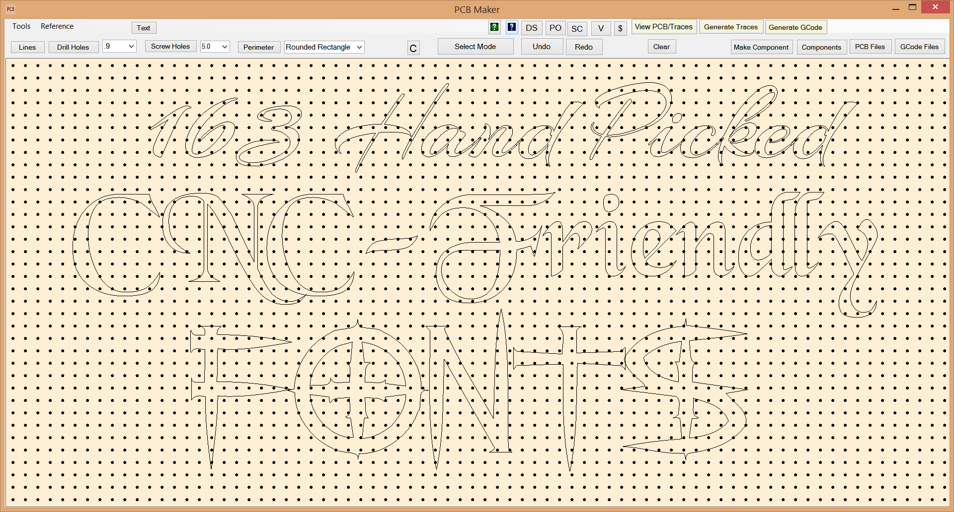
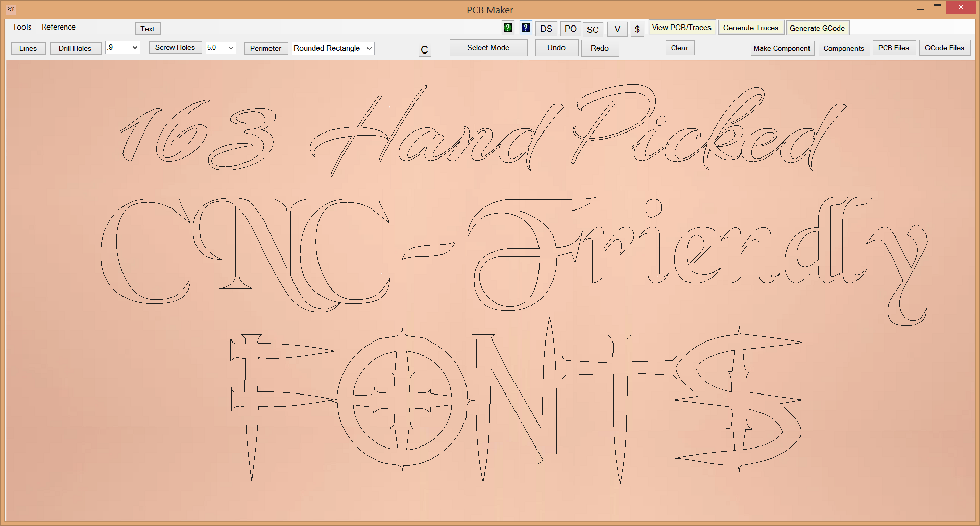
These 163 hand-picked fonts are the same set of CNC-friendly fonts included with our fantastic and gorgeous CNC GRBL controller software, NewRAD CNC.
NewRAD CNC has a high-precision Auto Level feature that is imperative for scratch milling PCB's on a CNC machine.
Scratch Milling PCB's with a Scribe bit is the Future ...and the "All World" Robin Debreuil
Scratch milling was first introduced to the public from a youtube video by Robin Debreuil, for whom we call "The Man", because of the incredible difference that "scratch milling" makes to all users. Robin was scratch milling pcb's using 3 passes, with XY offsets on the second pass, and with the spindle off, and using a high feedrate. We immediately loved the spindle being off idea, and the high feedrate. After getting up to speed with scratch milling, we found that turning the spindle on helps "clear out the chips" from the traces being cut into the copper, which allowed us to scratch mill pcb's with only 1 pass, thus significantly reducing the amount of time it takes to mill a pcb. We are able to mill a pcb using high feedrates, and only 1 pass, with no shorts. Special subtle details that we put into our GCode generated by PCB Maker allowed us to help make sure no copper debris is left in the tracks, thus no shorts on the pcb.
VBit Milling PCB's is now Obsolete (for us) (except for smaller traces like with SMD components.)
VBit Milling PCB's is now obsolete (except for SMD) because it MAKES TOO MUCH NOISE, plus it TAKES TOO LONG, plus the bits cost way more and do not last as long as scribe bits, and are highly prone to breakage. Plus V-bits can stick your finger easily, and they are scary to work with and handle. Whereas titanium carbide Scribe bits are unbreakable, much safer to use, stress-free to handle, cheaper to buy, can be re-sharpened and re-used many times, thus saving a lot of money over the long run. One scribe bit can last for about 2 or 3 fairly large pcb boards of say 8cm X 15cm. ...maybe 4 or 5 times if you were really pushing it. Scribe bits can be re-sharpened easily, but it seems that you do need to have a diamond tipped sharpening wheel to sharpen them, and you may have to build that tool yourself. But perhaps you could just buy new scribe bits until you have a large collection of used dull ones, and then maybe send that off to someone who could sharpen them for you. Or at that point, just build a machine yourself to do the job. In the end, you could end up with a nice scribe bit sharpening machine, and a large supply of scribe bits, and never have to buy another scribe ever. That is an attractive situation. And in the mean time, scribe bit sharpening machines may come available on the market to buy. V-bit milling should now only be used for the very finest of traces, like when working with SMD components. Some SMD traces can probably be done with a scribe bit, so using expensive and scary to handle V-Bits are simply not going to be wanted by most users for most pcb milling on a CNC at home. Adios V-bits!!!. Good riddance.
PCB Maker software is hereby dedicated to Robin Debreuil, for bringing his scribe bit pcb milling innovation to the public.
Robin's innovation helps, not only the millers of PCB's, but also their families, and neighbors too. Eliminating the horrible noise is the #1 benefit of scribe milling. Just thinking of all the fights it can help prevent, but also for the sanity of the user himself. Eliminating that horrible noise is the most important thing. But also, it is the time savings on how long it takes to mill a pcb. The money savings on recyclable scribe bits is also a big benefit. And eliminating the danger and stress of handling V-bits that could do so much damage to a finger or hand so easily. But the biggest benefit is reducing the noise to a very tolerable level. All of these benefits are attributed to "The All World", "The Man", Robin Debreuil. Thank you Robin!!! The noise was absolutely killing me.
Let the music play
We use a large 4080 aluminum extrusion machine with 20mm ball screws, and NEMA 34 motors, running GRBL firmware on an Arduino Uno, using NewRAD CNC as our CNC controller. Our CNC is big and heavy, so the dual Nema34 motors pushing the gantry axis is fairly noisy. But our machine is inside a sound proof box and that makes a big difference. It really helps a lot, but it cannot contain the noise of a spindle running at 10,000rpm. But since we can now run it at only 6500 rpm's when scratch milling with a scribe bit, suddenly the sound proof box can contain most of the spindle noise and most of the dual NEMA 34 motor noise moving the gantry. With music playing at only a moderate level, we can barely hear our large CNC machine running at all, when milling or drilling a pcb. And that is from the perspective of being in the same room with it. Our neighbors in the other apartments surely cannot hear a thing. We have milled PCB's as late as 11:30pm in an apartment building. This is a game changer to the max! This is why scribe pcb milling is so important to us. Thank you Robin Debreuil for fixing all the problems with milling a PCB at home. V-bit milling at a horribly noisy 10,000rpm with a feedrate that was slower than a snail crawling, was the biggest nightmare ever. I cannot even imaging using a V-Bit ever again. Scribe bit milling changed everything for me, and it will for all users all over the world. PCB Maker with NewRAD CNC brings it all together, in one seamless system, and that makes everything so much easier. We think our overall solution is a game changer.
PCB Maker is the only software that will let you easily design a circuit with great graphics, and then effortlessly produce GCode made specifically for scractch milling a PCB with a scribe bit, all in the same software. Two larges tasks in one seamless software. And the GCode produced is tuned specifically for using this scratch milling technique, and it includes special little tricks in the GCode that help ensure that there are no shorts on the PCB. And those little GCode tricks can really make all the difference between having a short, and not having a short. When PCB Maker is combined with NewRAD CNC, the entire process of designing a PCB, producing the GCode, and running a CNC machine to do all the milling and drilling, at home, is now quick and easy and with much less noise, for the first time. That is a very compelling reason to buy both PCB Maker, and NewRAD CNC.
Victory
The bottleneck has now shifted from manufacturing the PCB to designing the PCB, where it should be.
Before, it was relatively easy to design a PCB versus to how hard it was to make a PCB at home. That has now flipped. It is now harder to design a PCB, than it is to make it, and that is a win for everyone. You can mill and drill a relatively large 8cm X 14cm PCB in only 20 minutes. 10 minutes for milling, and 10 minutes for drilling. But even with PCB Maker's super easy and fast to use interface, it still usually takes us longer to draw up a circuit than it does to mill it. With some super simple circuits that is not the case. But a fairly complicated circuit can take quite a while to draw up. Often times while drawing up your circuit, you need information on a component's pin out, or you need to see a chip's data sheet, or you want to see some schematics with that component, or maybe watch a few videos on youtube or the video platform of your choice, about that component, or you need to search for pricing and availability of some part, ..and all of that takes time. But PCB Maker's interface makes all of those things easy too with Quick Search buttons. Another time saver, energy saver, and productivity enhancer.
Quick Search Buttons to see a Component's Pin Out, Data Sheet, Schematics, Videos, or Price and Availability

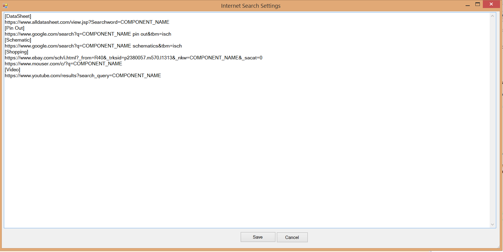
Just select the component you want to research, and click one of the little buttons at the top for Data Sheet (DS), Pin Out (PO), Schematic (SC), Video (V), or Shopping ($), and it will open up a browser to the website and search URL of your choice, using a variable for the Component Name. This is so handy and nice to have. If no component is selected, then it will use the last component added. You can edit the Quick Search URL's in "Quick Search Settings" in the "Reference" menu.
Quick Search Settings
To edit the Quick Search URL', click the Reference menu, then click on the "Quick Search Settings" menu item. Note that COMPONENT_NAME is used as the variable for the component name in the search URL.
Project files for sharing your ideas and designs with others
A Project file in PCB Maker is just a normal zip file that can include multiple documents for things like PCB drawings, GCode, pictures, text, html, links, and Arduino code. This is a great feature that will let users create a total solution and share it to other users. A user will be able to upload their "project files" to our server.
PCB Maker is the Software You Have Waited For
Buy PCB Maker here
Features Free Version PCB Maker Design PCB Drawings Yes Yes Save PCB Drawings Yes Yes Generate Traces Yes Yes Generate GCode No Yes View GCode run in 3D Viewer N/A Yes Create you own components Yes Yes Generate And Print Toner Transfer
for etching PCB's with AcidYes Yes Generate And Print Solder Mask
for using with UV paintYes Yes Create Project files for sharing your ideas. Yes Yes Price Free 149.95
Purchase a license here ==> Click "Buy Now" button ==>
* After purchasing a license, you need to activate the license in order to access all the features that you purchased.
How To Activate License After Purchasing
To activate your license, run PCB Maker software, click on the Tools menu, then click Activate License and enter your Paypal address. You should then get a message box that says "Thank you for purchasing PCB Maker", and your software will then be activated for full usage of all features purchased.
Thank you for purchasing!
=====================================================================================================================================
Extra Features in the Free Version
Generate and Print a Toner Transfer sheet
For those without a CNC, or Users of the Free Version.
Start with a PCB Drawing...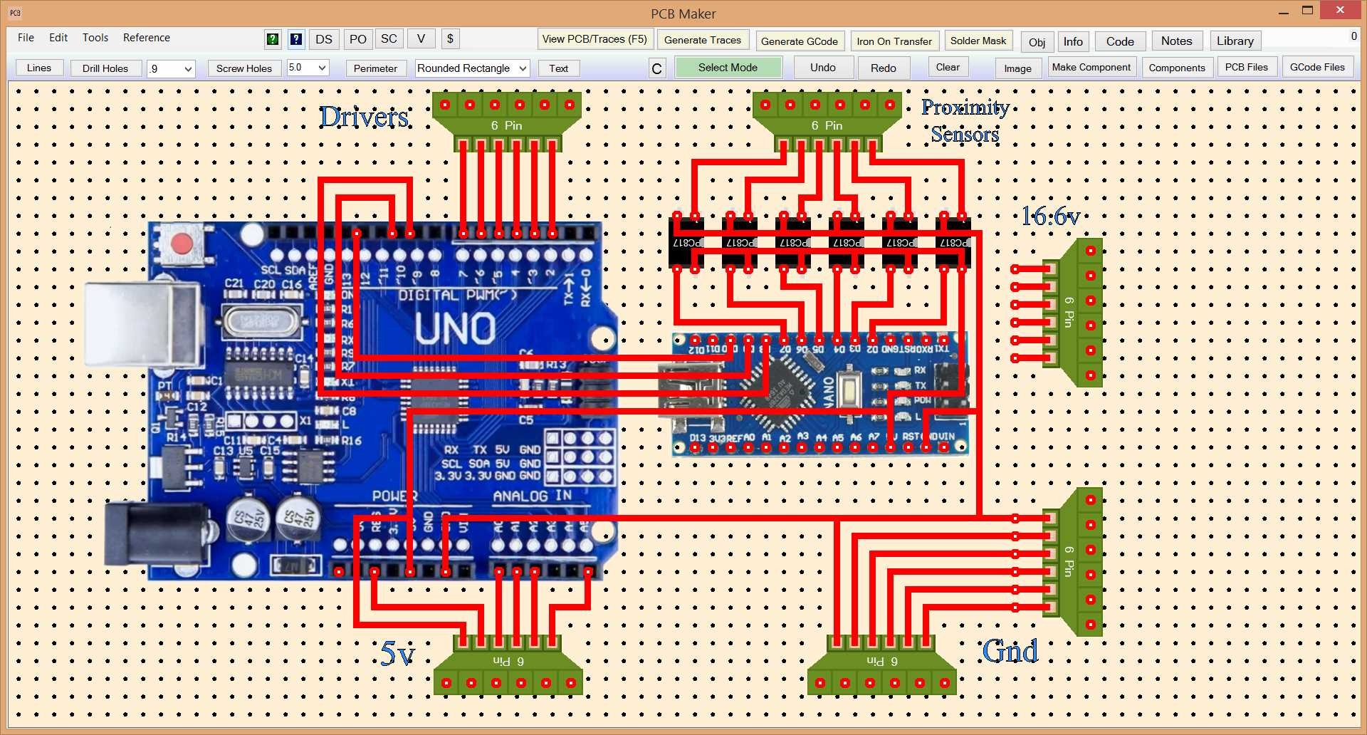
Then Generate and Print a Toner Transfer sheet.
Generate and Print a Solder Mask
Use UV paint, and a UV light, and our Solder Mask printed onto a plastic sheet for blocking UV light over the drill holes.